nRF24L01+ Radio Communications using RF24 over SPI-GPIO
The first thought that came to my mind when I read that was: “wow, that’s a remarkably complicated-sounding name for a simple blog post”. I’m looking for replacements, so please drop a few in the comments.
Anyway, back to business. The point of this post is to outline the procedures involved in using nRF24 radios (by now, you’ve realized I must really like them ) on a Raspberry Pi via a bitbanged SPI connection. Normally, you’d simply compile and install Tmrh20’s RF24 library, wire up the module the Pi’s dedicated SPI pins, and then go forth from there. However in my last post, there was the possibility that the hardware/dedicated SPI pins would be used for some other purpose (oh I don’t know, providing wired ethernet maybe?) and would be unavailable to do this. I then talked about the moderately-involved process of providing a software-based/bitbanged SPI peripheral which could then be used for some other purpose. This post aims to illustrate one such possibility.
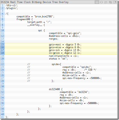
The RF24 library accesses the Pi’s hardware SPI controller via the BCM2835 library. However, it also supports SPI communications using driver (libraries) like MRAA (Intel Galileo/Intel Edison, etc) and SPIDEV, the latter of which is the standard Linux userspace driver for SPI devices. Since spi-gpio provides an SPI device with SPIDEV capability, this is the way to go.
Support for SPIDEV in RF24 was apparently meant for the BeagleBone Black, although any SBC supporting SPIDEV would work. The SPIDEV backend (which is contained in the utility/BBB/spi.cpp file in the RF24 source tree) is hardcoded to use either /dev/spidev1.0 or /dev/spidev1.1 as these are the SPI bus files available on the BBB presumably. However, the SPIDEV file created for our spi-gpio device is (at least in my case, YMMV) /dev/spidev32766.0, so we need to edit this spi.cpp file to reflect this. Within the file, in the SPI Begin() function, the stock configuration looks like this:
 In the case of the spi-gpio device, there is only a bus 0, based on my configuration. Rather than make any potentially-confusing changes, I simply did this:

That is, I commented out the entire BBB section and added the highlighted line above, in effect ensuring that regardless of the supplied bus number, /dev/spidev32766.0 would be used. If your own overlay had more than one clock select line and you wanted to be able to specify, you could simply edit the stock code in the BBB section to reflect that.
Once this was done, I simply ran make –B RF24_SPIDEV=1 as the docs said to do, and the build completed successfully. I then ran a make install and that went successfully too. Finally, (the module was already wired up at this point), I tested out the gettingstarted program (taking care to use an appropriate constructor) and Bob was my uncle.
So in summary, all you’d need to do to enable RF24 work over an spi-gpio device would be to edit the utility/BBB/spi.cpp file and explicitly set the SPI device used to your spi-gpio device, then recompile and reinstall the library.
Ps: I’m still mulling over the static MAC address thing for the ENC28J60. Hopefully more on that in a bit.
Auf Wiedersehen!
PPS: Happy New Year!!!
EDIT: For some reason, running the gettingstarted.cpp program (after compiling it) for the first time after the Pi has booted will result in a segmentation fault. Any subsequent runs work fine. Seemingly, the first run after every boot will result in a segmentation fault but subsequent runs (during that same cycle i.e if you don't reboot) will work fine. However, running the program as root (by prepending the invoke command with sudo) doesn't appear to have this problem. Weird. I don't think this problem is localized to the gettingstarted.cpp program though.
Anyway, back to business. The point of this post is to outline the procedures involved in using nRF24 radios (by now, you’ve realized I must really like them
The RF24 library accesses the Pi’s hardware SPI controller via the BCM2835 library. However, it also supports SPI communications using driver (libraries) like MRAA (Intel Galileo/Intel Edison, etc) and SPIDEV, the latter of which is the standard Linux userspace driver for SPI devices. Since spi-gpio provides an SPI device with SPIDEV capability, this is the way to go.
Support for SPIDEV in RF24 was apparently meant for the BeagleBone Black, although any SBC supporting SPIDEV would work. The SPIDEV backend (which is contained in the utility/BBB/spi.cpp file in the RF24 source tree) is hardcoded to use either /dev/spidev1.0 or /dev/spidev1.1 as these are the SPI bus files available on the BBB presumably. However, the SPIDEV file created for our spi-gpio device is (at least in my case, YMMV) /dev/spidev32766.0, so we need to edit this spi.cpp file to reflect this. Within the file, in the SPI Begin() function, the stock configuration looks like this:


That is, I commented out the entire BBB section and added the highlighted line above, in effect ensuring that regardless of the supplied bus number, /dev/spidev32766.0 would be used. If your own overlay had more than one clock select line and you wanted to be able to specify, you could simply edit the stock code in the BBB section to reflect that.
Once this was done, I simply ran make –B RF24_SPIDEV=1 as the docs said to do, and the build completed successfully. I then ran a make install and that went successfully too. Finally, (the module was already wired up at this point), I tested out the gettingstarted program (taking care to use an appropriate constructor) and Bob was my uncle.
So in summary, all you’d need to do to enable RF24 work over an spi-gpio device would be to edit the utility/BBB/spi.cpp file and explicitly set the SPI device used to your spi-gpio device, then recompile and reinstall the library.
Ps: I’m still mulling over the static MAC address thing for the ENC28J60. Hopefully more on that in a bit.
Auf Wiedersehen!
PPS: Happy New Year!!!
EDIT: For some reason, running the gettingstarted.cpp program (after compiling it) for the first time after the Pi has booted will result in a segmentation fault. Any subsequent runs work fine. Seemingly, the first run after every boot will result in a segmentation fault but subsequent runs (during that same cycle i.e if you don't reboot) will work fine. However, running the program as root (by prepending the invoke command with sudo) doesn't appear to have this problem. Weird. I don't think this problem is localized to the gettingstarted.cpp program though.

Comments
Post a Comment